Mounting FlipFlat and SQR
Warning
Before starting please check if this solution also work for your environment. This means please check carefully dimensions and devices. This setup might not work for you.
Warning
Changes on all devices are made at your own risk!
Description of parts for FlipFlat / SQR holder
Note
Please use adequate parts if you would like to follow the example. In my setup the diameter of the dew shield is 121.3 mm. It’s a Teleskop-Express Photo Line TLAPO1027-FT.
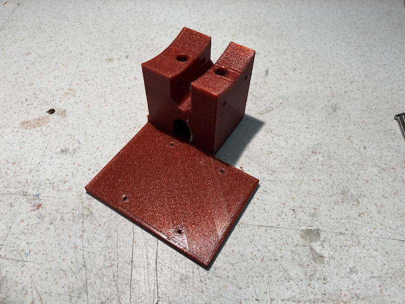
2 x M4 x 30 mm for connection dew shield ring to holder attachment 2 x M4 x 15 mm for connecting the two dew shield rings 2 x UNC #6 x 1/2 for connecting the Alnitak FlipFlat to the holder 4 x M3 x 25mm self cutting screws for attaching the unihedron to the holder 1 base ring 1 attachment ring 1 holder
Parts: Unihedron and FlipFlat
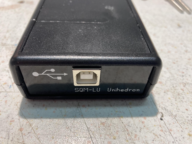
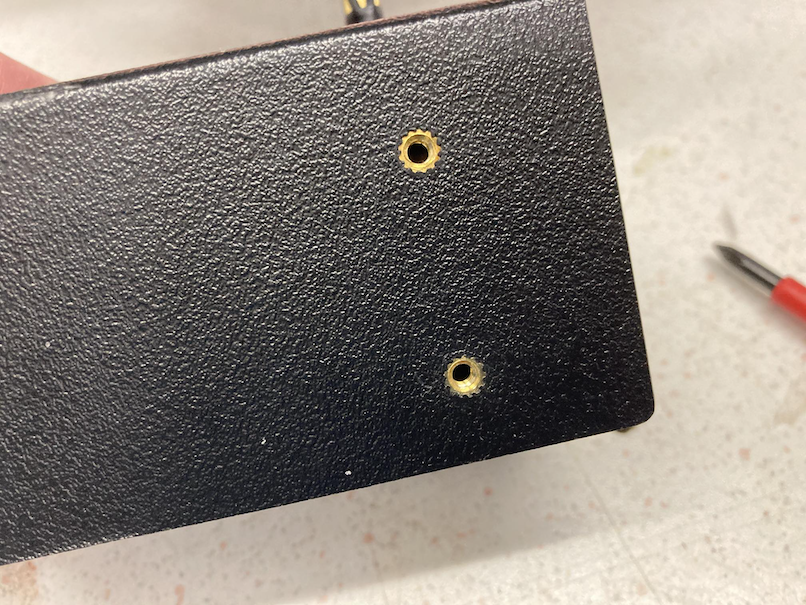
Back of the unihedron sqr with the USB interface.
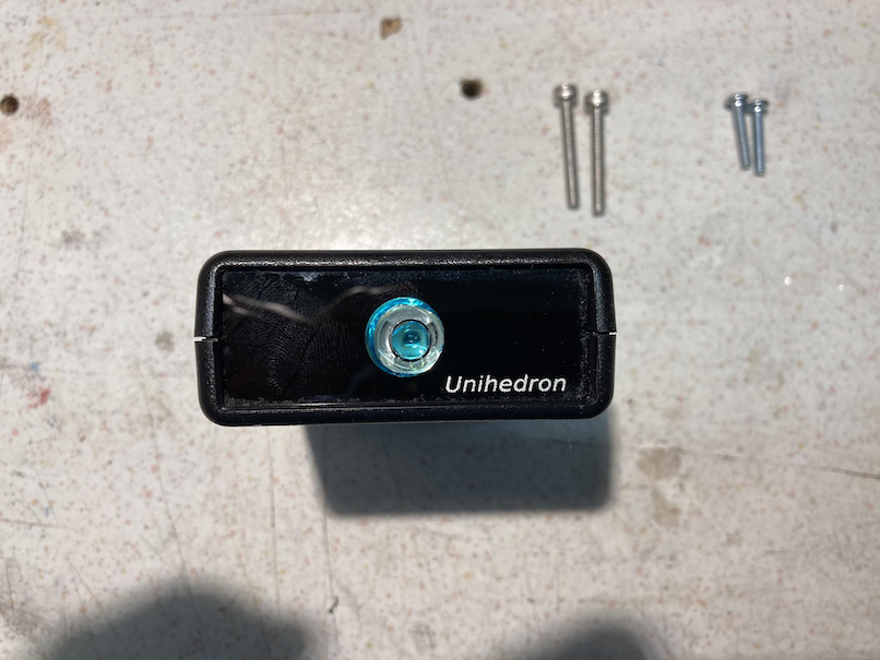
Front of the unihedron sqr with lens.
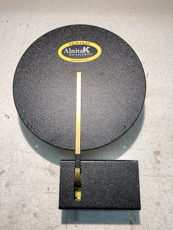
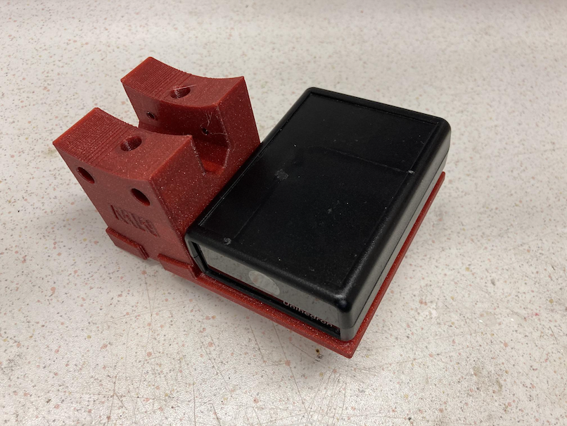
Alnitak Flip Flat device without any original holder part attached.
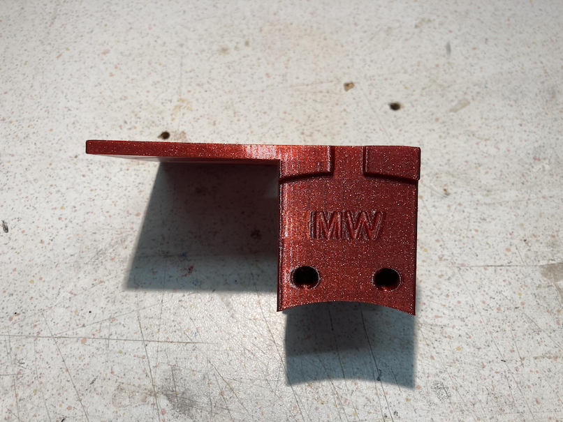
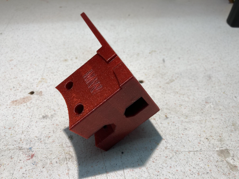
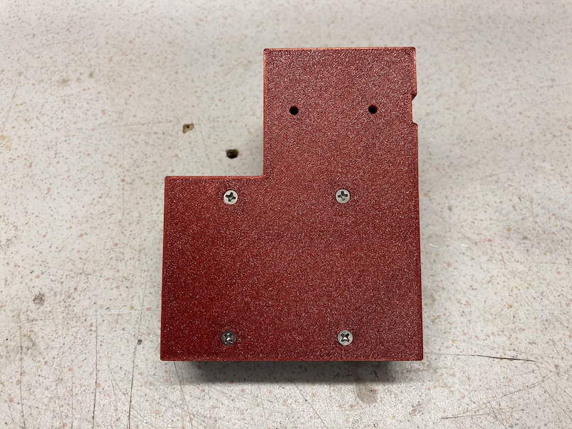
The holder which fixes FlipFlat and unihedron and makes the link to the dew shield ring.
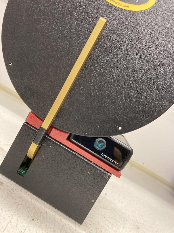
1. Step: attaching the unihedron to the holder
Please remove to original 4 screws, which close the package of the device from the button. Put the device upside down below the holder part and use the 4 self cutting screws to fix the unihedron to the holder.
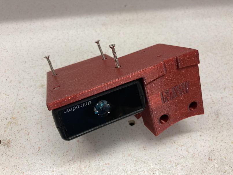
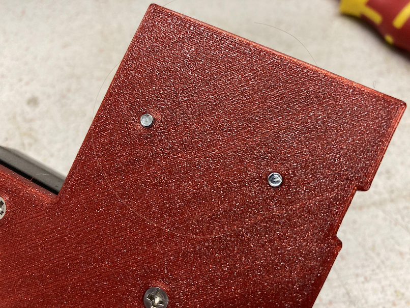
The screws should fit easily and should not stand out of the surface.
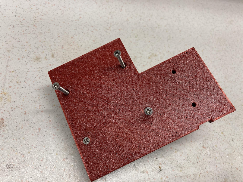
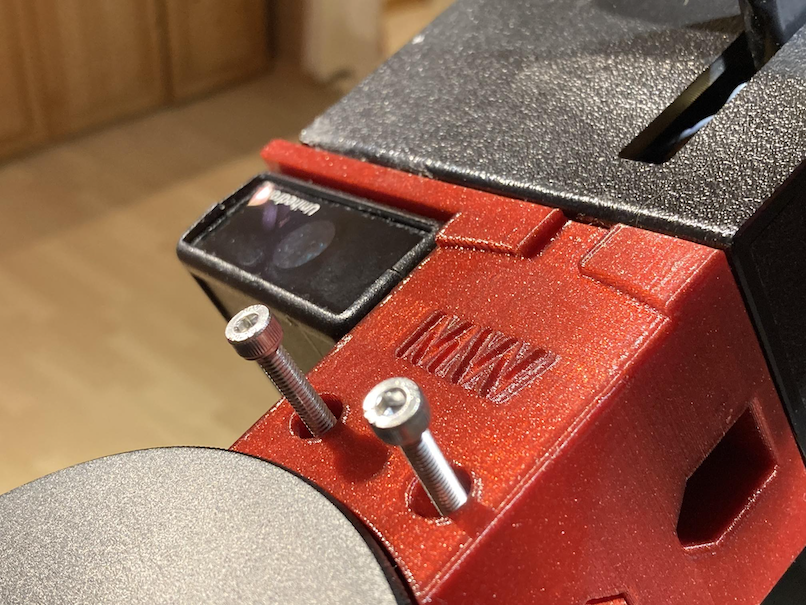
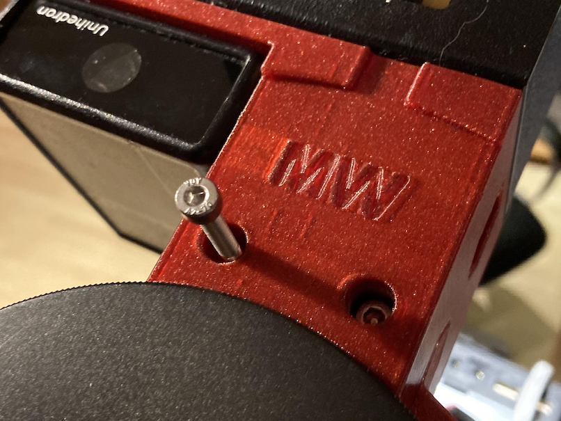
2. Step: screw on the FlipFlat to the holder
Plug in the screws for the FlipFlat
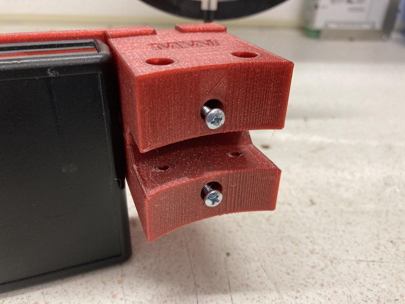
and turn them until they are equal to the surface of the holder.
Both screws should fit into the thread nut of the FlipFlat
Hand tighten the screws.
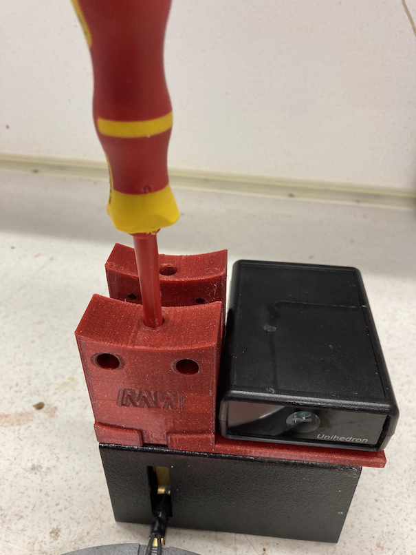
Now you got the holder with the attached devices.
3. Step: attach the two drew shield rings
The OTA ring with the nose should be on the upper side of the OTA the second on the lower side. Use two M4 screws to tighten the connection. As I used PETG, I did not need a thread nut. please check this in your case. The OTA ring should be directly linked to the drew shield end.
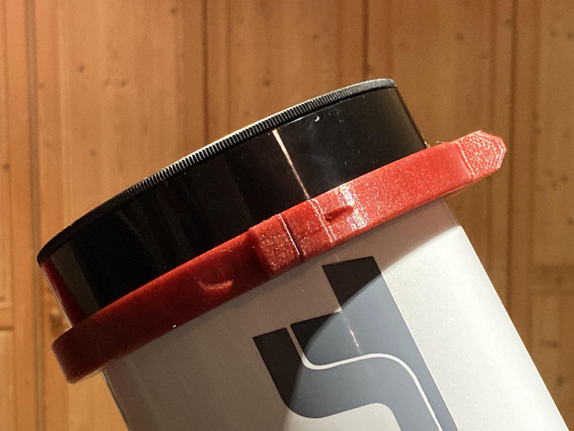
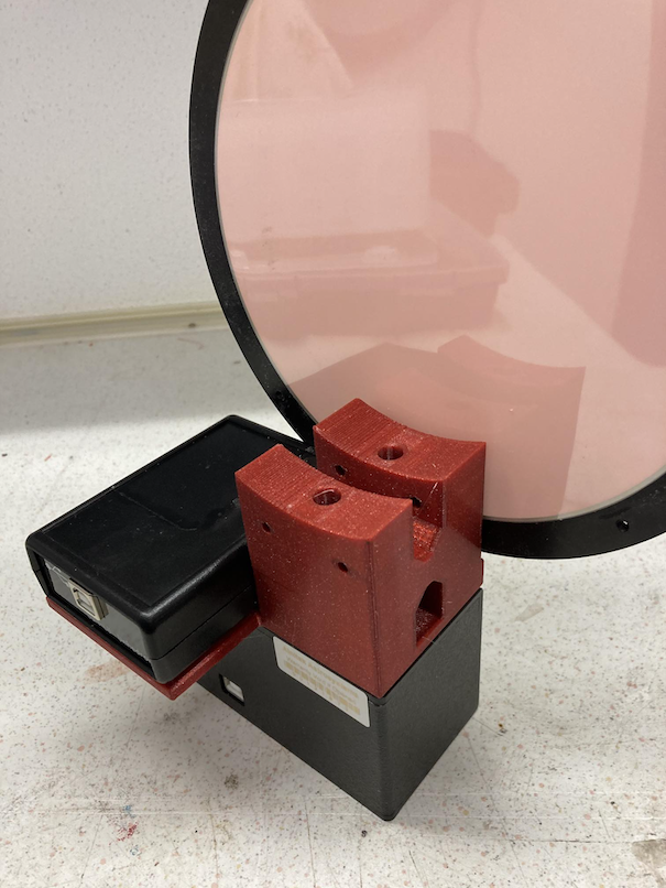
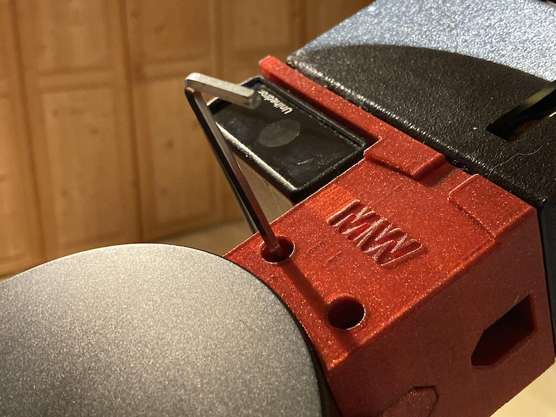
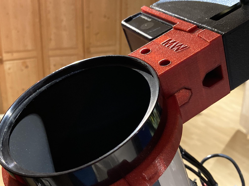
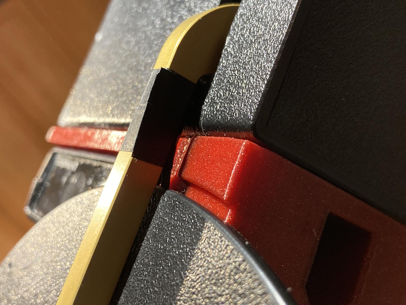
4. Step: attach the holder to the dew shield ring nose
The holder slips exactly on the nose of the dew shield rings.
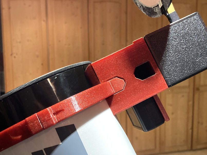
It will be fixed by 2 M4 screws. These screws are inserted from the front.
To tighten it, please use an allen key.
Finally you made it.
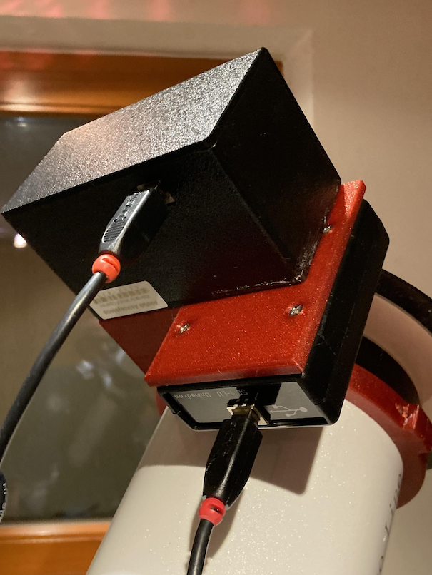
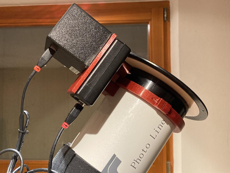
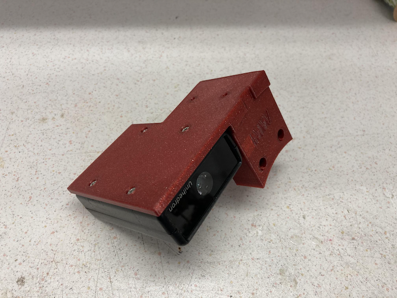
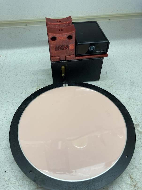
Assembled setup:
Finally you get an clean setup which both devices connected.
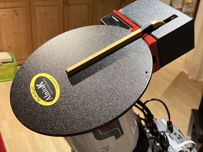
Connect the USB cables and your are set !